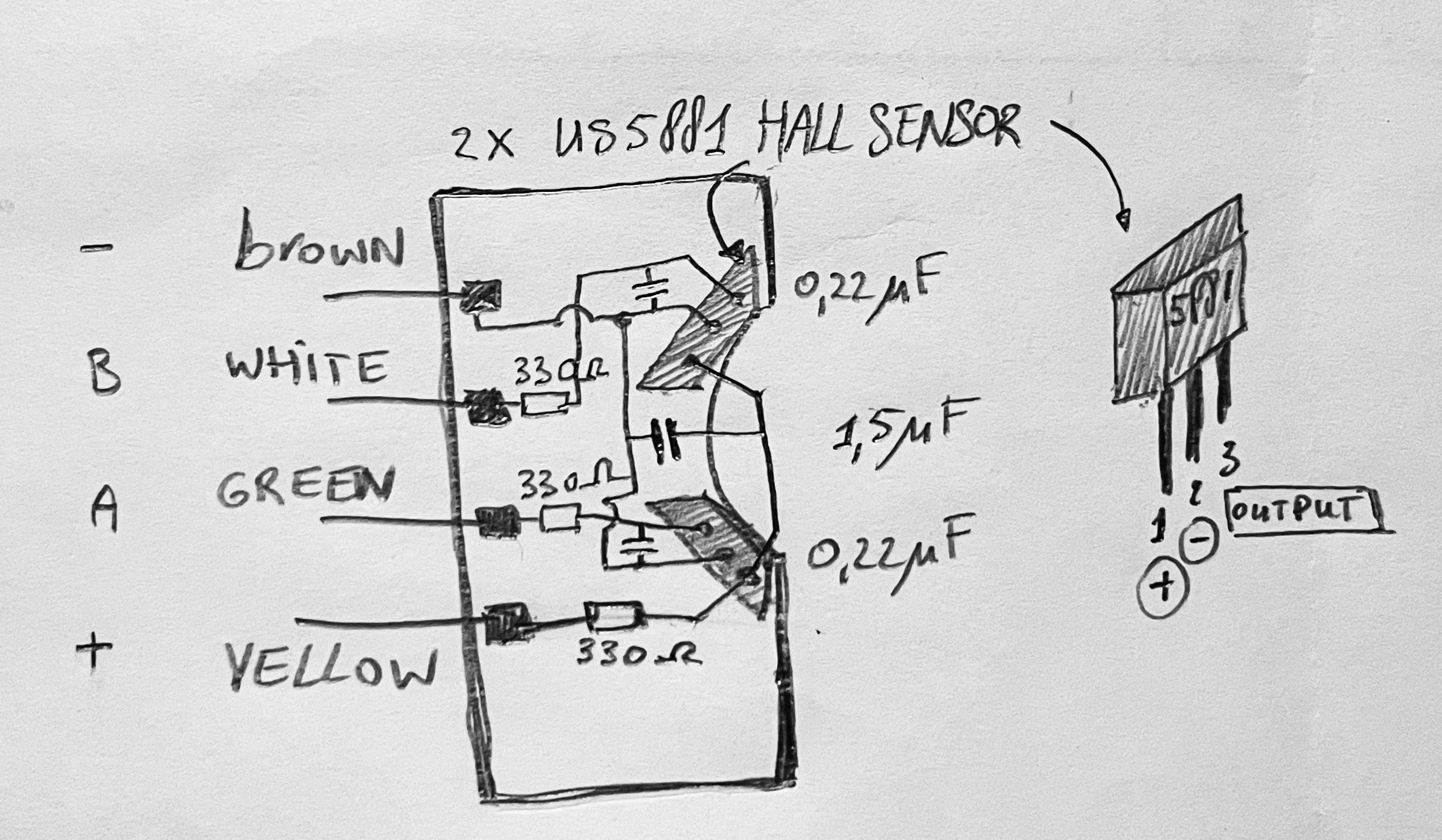
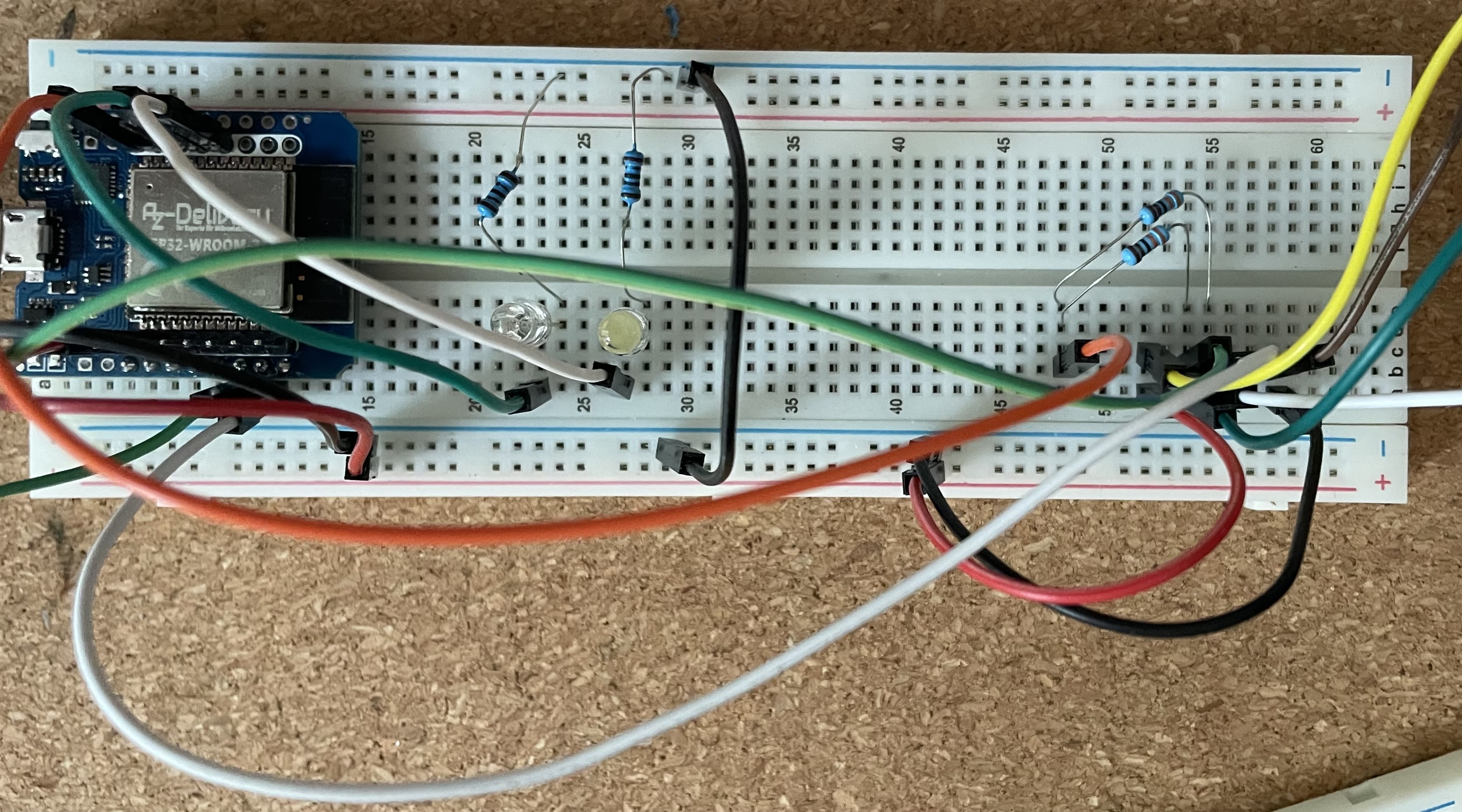
Short explanation of the very simple sensor circuit:
The 0.22 uF ceramic capacitors filter high frequency signals since we expect in this application lower than 50Hz signals. the 1.5uF capacitor is power supply stabilisation, in combination with the 330 Ohm series resistor between the yellow terminal and the + of the hall sensors . The 330 Ohm resistors in series to the A and B sensor terminals limit the current the sensors may draw.
The A1131 is a bipolar (latching) Hall switch (options: unipolar, omnipolar, latching/bipolar)
One polarity of magnetic field turns it on.
Opposite polarity is required to turn it off.
replacement as a bipolar hall sensor is the well known US5881 does include a open drain and schmitt trigger and voltage regulator built into its design. The build in hysteresis ensures clean, stable switching behavior in digital applications. The operating voltage is from 3.5V to 24V.
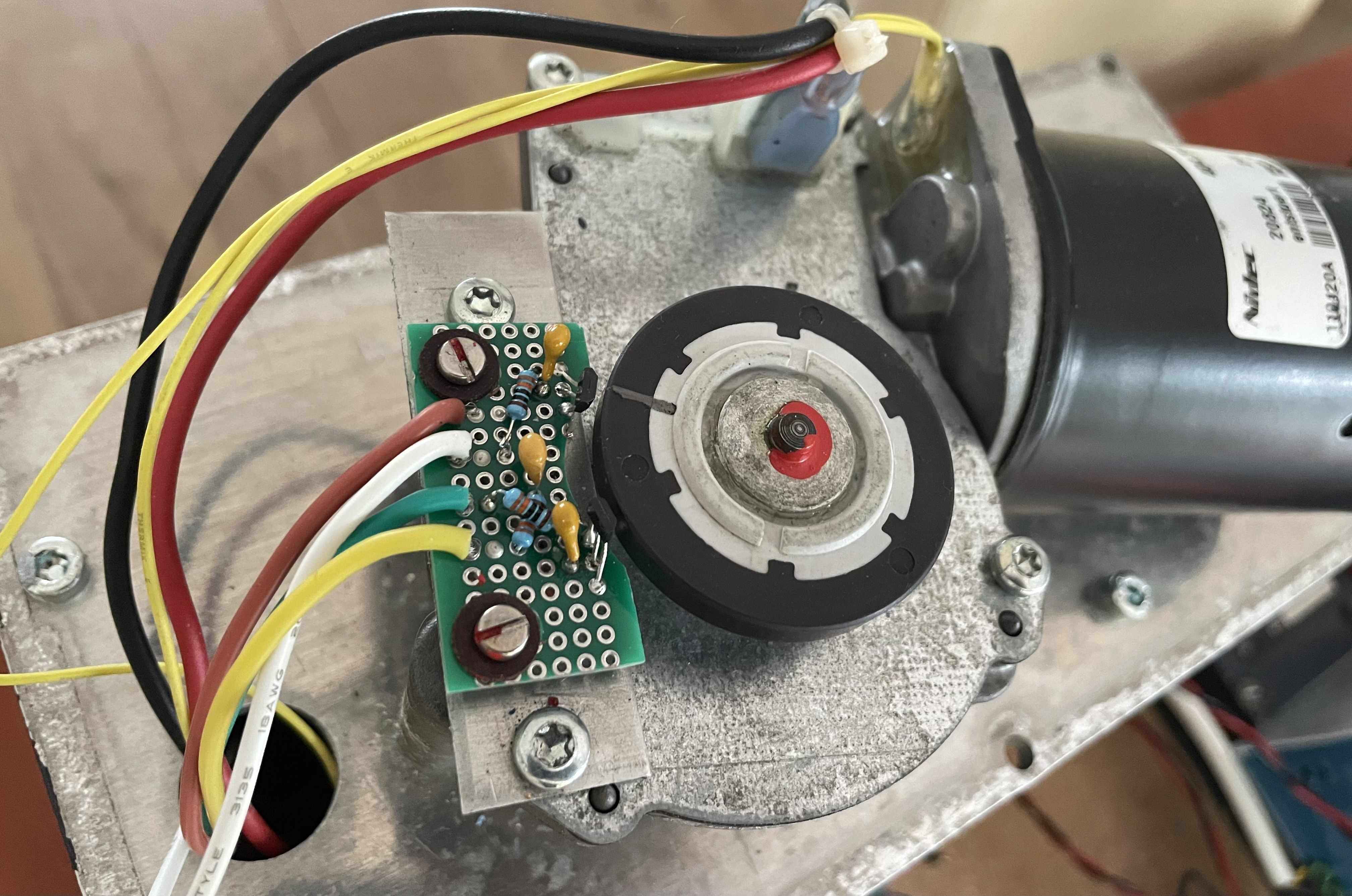
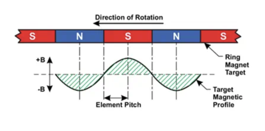
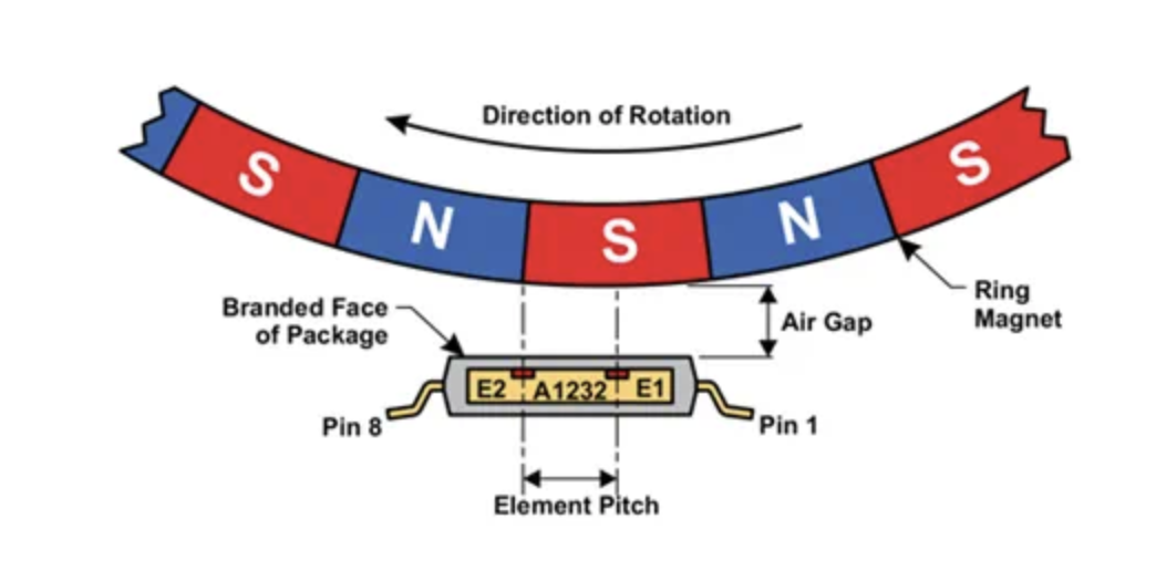
As shown in the video top right and below, the magnets in the wheel pass the two hall sensors, resulting in a specific binary signal pattern (shown below on this page) which reveals the rotation direction and speed of the wheel.
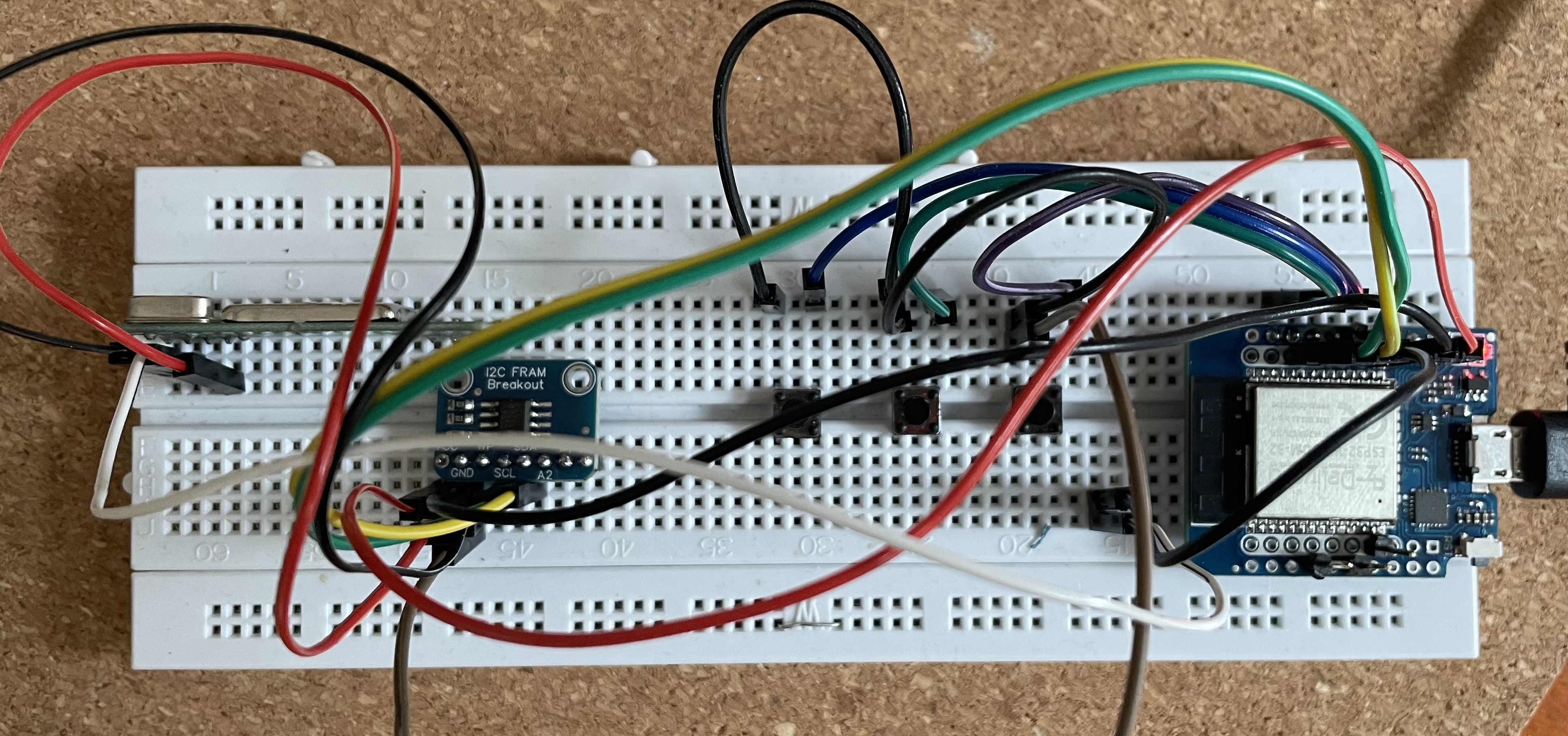
Write data to FRAM in a reliable way, so we write 3 times and when reading we 2 out of 3 schould match:
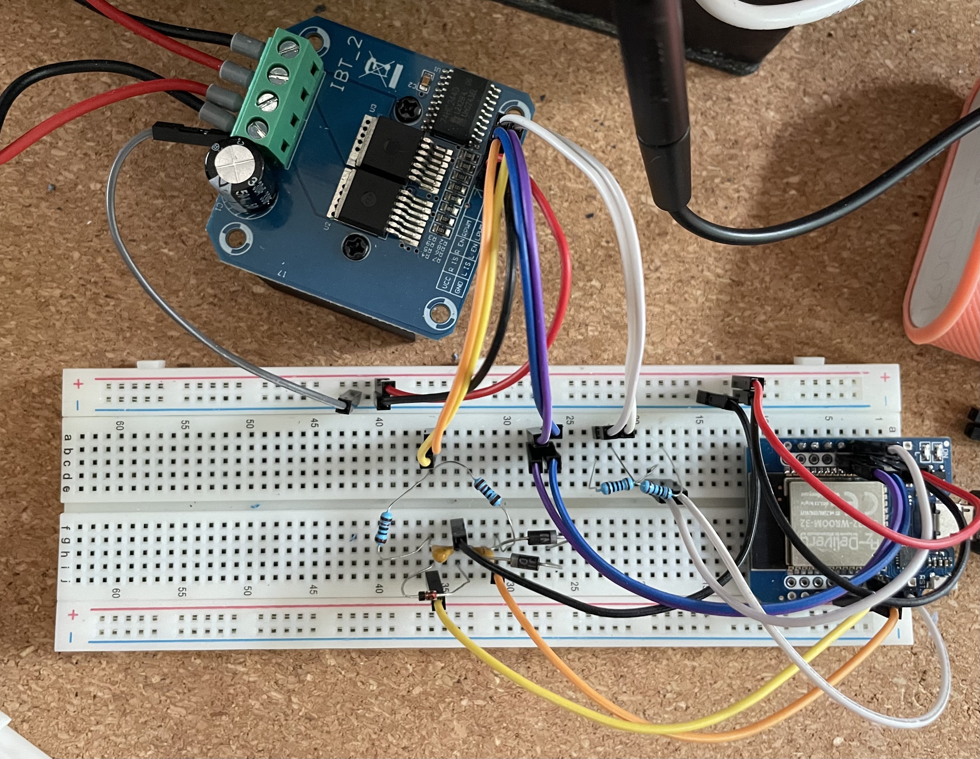
The remote control with a webserver (open stop close and max speed, ramp time, wait time for reverse and current limit) and 3 physical buttons pin 25, 27 , 32 for open stop and close :